Selection of Slewing Bearing Size
Factors need to consider when selecting a slewing ring
When determining the most efficient and economical slewing bearing for a specific application, the following factors need to be taken into consideration:
• loads added on the bearing
• frequency of oscillating movements
• application type
• bearing size most suitable for the application
• torque applied to the gear
Selection of Slewing Ring Bearing Size
The selection of slewing bearing size can be based initially on the dynamic and static load ratings of the bearing, in relation to the applied loads and the requirements regarding reliability and service life. Values for the axial dynamic load rating C and axial static load rating C0 usually can be found in the products data sheet.
When determining slewing bearing size using the static limiting load diagrams, additional forces should not be ignored. The forces are different based on the type and mode of operation of the machine and operational requirements regarding service life and reliability. This is done by multiplying the resulting axial load and tilting moment by a load factor fL.
Far = fL x Fa
Mtr = fL x Mt
where
Far = maximum rated axial load, kN
Fa = resulting axial load applied to the bearing, kN
Mtr = maximum rated tilting moment, kNm
Mt = resulting tilting moment acting on the bearing, kNm
fL = load factor

Using the calculated values for the maximum rated axial load Far and the maximum rated tilting moment Mtr , the requisite slewing bearing size can be obtained from the appropriate static limiting load diagram, shown together with the slewing bearings in the product data sheet. Each diagram contains two curves per bearing; the solid line shows the
raceway capacity and the dotted line shows the bolting capacity (as below). The points, where the plotlines of rated axial load Far and the rated tilting moment Mtr intersect, must always be below the capacity curves, i.e. inside the blue zone. If the points of inter-section (red) are above the capacity curves, the bearing is not suitable for the application.

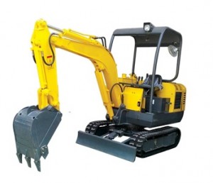
Example of choosing a slewing bearing size for a mini excavator.

We are going to select a slewing bearing with internal gear for a mini excavator, its operating conditions as below:
- resulting axial load applied to the bearing
Fa = 65 kN - external radial load applied to the bearing
Fr = 12 kN - resulting tilting moment acting on the bearing
Mt = 120 kNm
The following is considered:
The value for the load ratio Fr/Fa = 12/65 = 0,184 lies within the permissible range Fr/Fa≤0,6. Therefore, any series of four-point contact ball or crossed cylindrical roller slewing bearing can be used.
With fL of mini excavator = 1,33 the maximum rated axial load and maximum rated tilting moment is calculated:
Far = fL x Fa = 1,33 x 65 = 87 kN
Mtr = fL x Mt = 1,33 x 120 = 160 kNm
Then a bearing that adequately meets the needs of the application can be obtained from the product catalogues.

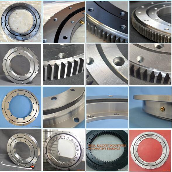
e.g. RKS.062.20.1094 medium size four-point contact ball slewing bearing with an internal gear,

e.g RKS.162.14.1094 medium size crossed cylindrical roller slewing bearing with an internal gear
If you are not a professional, don't worry, our technicians will help you with slewing bearing size selection, you only need to let us know bearings' operating condition, we'll offer a whole solution for you. (brs@brsbearing.com)

